Tuesday 11 May 2021

Let's do the twist, like we did last(this) summer

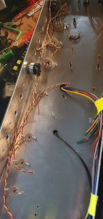
 Time for some wiring... kind of wanted this to be like the BE100, so instead of the neat parallel socket wiring on the slo, decided to do the full twisted wire experience. Which looked tedious and time consuming, and spolier alert, it is...

So, I also decided to do the whole twist a large length of wire using the door. This was pretty satisfying to be honest, and much easier than my last attempt, with a bonus of not bruising the living shit out of my legs. Pretty much tie wire to door handle, stand on other side of room, attach wires into drill, then slowly twist, and walk towards door. I ended up with a nice length, although some bits in the middle ended up a bit bobby, but seeing as I now had a lot of it, no problem, just cut the ugly bits out later. 

Anyway, I ended up with a rather long piece, as can be seen in the pics. Next up, roughly cut pieces with extra so i can wire between sockets and have it flush against the edge of the chassis later. Want it to look neat after all, especially as noone will ever see if aftrer the amp goes into it's home, but I will know it's there. and I'll have some nice pics for this blog. 


As a quick recap, twisted wires are so the distance between wires stays the same, and is one of those "reduce noise and hum from the AC voltage with 50/60Hz cycle hum from the power supply. There's a few other things you can do like elevating the heaters as well, which I'll be doing, but this is one of the bits that is quite important.


Anyway, lengths all cut, just lined them up where they were supposed to go. At this point I should have added the small tag board, but forgot. Ended up being a lot lot more fiddly to add this later, so I should have done it, like, at this point now. 

Not much else for this bit really, time to get out the soldering iron. And resist the temptation to lick it to test if it is on. Done it once, never ever ever again. Would NOT recommend.


So, wiring started. Choose a colour for each pin, and make sure this colour ALWAYS goes to that pin. Put the incoming AND outgoing wires in the socket pins (2 and 7 on octals) and wire. Then cut wire to next socket to length, and repeat the process. I actually found using the screw of the socket was handy as a guide to hold in place and loop. Also the alpha wire as it's quite stiff lends itself well to this. Just arrange, push into corner fold of chassis, run top next socket repeat.


Then, same with the preamp, sockets.

I read somewhere that whatever you tied to pin 2 on octal power sockets should go to pin 4+5 (which in AC are soldered together, and pin 9, the centre of the heaters for triodes (as a double heater, one for each side require 6.3V each, with DC you'd not connect 9 and just run 12V across 4 and 5 with them not soldered together))

pin 7 then goes to pin 9. 

I had them (as per pic) with a J shaped run down to 4+5, but a friend (not the oracle, but another version, lets call him the allknowing tinker, who is basically a mad scientist/amp tech I've know for years) pointed out this was bad, and to just run the wiring through the centre of the tube socket. So in later pics you'll see that change. Makes sense really. 

He also told of a prophecy that if you have different winds per twisted section per square inch for each of you runs (preamp run is one, power another etc) that this helps stop creating induction noise. If I'd known before I started this, I'd have done it for OCD, but at this stage of the game I'm going to leave it for the next build.


Lastly, as on a roll, I cut the wires to length from the output transformer to the impedance selector. Because I wanted a my little pony moment, I braided them together. I doin't know why. Just seemed like something I wanted to do, and as it's my amp, I'll do what I damn well like.

I do have to say that this took a lot longer than I thought it would, and was not really that much fun, but having done it, and it looking neat, I'm quite pleased with it for a first attempt, and everything would be awesome, except...

...excpet that having had a look at the layout diagram, the V1-3 tube sockets actually use a DC heater supply. Fuck. I've kind of decided that unless ithere is bad noise that I'll leave it like this. Rewiring will be a pain, not helped by having soldered together the 4+5 pins of every single socket, and the orientation of the sockets being upside down from the layout (something I bet I'll come to regret later on).

I'll just try to mitigate it by adding elevated heaters. Besides, the slo isn't that noisy, and that uses AC heaters through, even on the sensitive V1-2 tube gain stages.

I'm thinking I'll end up hot gluing the heater wires at strategic places once the amp is more done to hold them in place and for neatness, but maybe not. I'll see later on. I've also lost all those awesome plastic square things I used to tie down cable runs neatly in the last build, even though I know I have a huge bag of them. Maybe I should look a bit harder, as they'll definitely be useful.

Next up, it'll just be some power wiring to get rid of some of the long transformer leads which are definitely in the way.

Finally doing the dirty... drill me yeah baby yeah

 Oh yes, after lots of boring bits, bagging components, placing multiple orders, finally, finally, finally I've got round to doing something that is actually interesting. Also as I've neglected to post anything for a while, this could turn out to be quite long... I'll probably split it over a few to segregate by section of what i've been doing, so chassis work, mounting, heater wiring and hooking up power wires. Oh, I also seperated components into seperate boxes. One for chassis bits, other for electrical components. Reminds me I still haven't ordered the bits I forgot to get, should really get on that as there's a few things I didn't think of, and annoyingly, a few bits that were not on the BOM (even MORE annoying)

So, what have I been up to? I left you, dear reader, on a proverbial cliffhanger (well, maybe not, but if you're an accountant, or have a fetish for excel spreadsheets, I do apologize for the sheer amount of excitement contained in the last post). Since then, well, a lot of stuff involving power tools has happened. And screws. So If you get excited about drills, screws, nuts, bolts and twisted wires, then this post is most definitely for you, so go get your Kleenex, sit back, and in the words of Frankie Goes to Hollywood: "Relax"


Mr punchy the hole marker

Anyway, first off, I did a load of component mounting, and drilling of holes. To start off with, I positioned the PCB on the inside of the amp. Normally I'd choose a location like I did with the slo, but as the chassis was sort of predrilled already for the board the guy that makes them sells, I figured I'd try and use as many of the same holes, or at least one, if possible. Turns out, a few were there, but others, not so lucky. Took the board out, and marked the mount holes on the PCB with tape to be able to tell where they are. Then I positioned the board across as many of the preexisting holes already. Following that, taped the board down, and using a permanent marker marked the positions of the new holes. Simple enough eh? Also, I found this a bit easier than the last time where I used a cutout of a printed copy of the board. At least this way it means that you now it is to scale, as, well, it is the actual board and not a copy...


Following that, removed the board, use the punch marker thingy to punch a small indentation to use as a place to position the drill bit, and drilled pilot holes. Following that, drilled all of them out to 3mm with the appropriate drill bit. Then, as I don't like the look of screws sticking out from the chassis (pan heads) I went and countersunk all of them with the appropriate countersinking drill bit, which is just an invaluable tool. This time I have one that is standalone, and doesn't require clamping onto a drill bit. Means I'll hopefully break less drill bits. I've also been using an electric drill, whilst not as violent and quick as a mains one, it does mean I seem to be a bit more controlled, so that's nice. I did find, however, that when using the step drill bit with it that it is not powerful enough to actually do anything fun, so powered drill still rules for that...

So, once that was done, i found some standoffs (10mm) and figured I could use them, but quickly discovered that I can't as i'd need 5mm length screws either side. So I've ordered some 20 and 30mm ones. I'll have to figure out what I can get away with once I've populated the board and see how much clearance there is to the bottom of the chassis with those deliciously fat lethal voltage carrying capacitors (them smoothing ones for the power supply, the ones you don't want to lick unless you're either a little bit thick, or have a death wish). Besides, I'm also going to be mounting transformers and the choke, so there needs to be clearance for those bolts.

So next up, I went about mounting transformers and choke. Unlike last time where I made paper cut outs, I went with a place and mark approach like the PCB above. I used masking tape to help position (giving me an edge to line up the transformer against) and thus also allowing clearance on sides and front/back which I'll need for putting it into a headshell eventually. once positioned, I then used the same permanent marker to colour in the area where each bolt should go (4 per transformer, 2 for the choke). At this point for transformer orientation and placement I had a look at some online pics of a be100, and just roughly eyeballed it to be the same. 

Again, using mr punchy the metal poking hammer stick device, got small indents for the drill to be placed on, and drilled a pilot hole, then widened to 3mm, then widened to 5mm for transformers and 4mm for the choke. I'd found that when drilling the pcb mounts that I got burring on the inside of the chassis, and that that led to wonky strandoffs unless cleaned up, so I did a light countersink to tidy up the holes and remove excess metal from the inside of the chassis.

That all done, I used tape (again) with the transformer in place to mark out where I wanted to drill holes for the wires to go through. For the choke I reused a PCB mount point I somehow drilled out of position, in aid of that not going to waste. PCB has enough mount points so this isn't an issue, and also keeps things relatively neat without a random hole that when stared out asks many questions. That and it looks crap. At this point I got to use the step drill bit. Too much fun, so you've got to stop yourself from making massive holes and practice restraint. You don't want it looking like goatse, but more like a hole that is just the right size. Plus, you want a grommet to fit in it (nicve rubber surround to stop the chassis cutting into the wires, as as much as attaching a few hundred volts to what should be ground is, it's not advisable, as the effects thereof are apparently a lot less pleasant than what cartoons implied they'd be when you were a kid...


That all done, put the grommets in and then I mounted transformers with bolts after feeding through all the wires. I had forgotten to get some, but found out that racks screws are the exact size (M5) that I need, so used them. Plus, they were black, so matched the transformers. Colour coding is important you know. Mounted choke, and then all done for this bit.

Finally moved on and put all the tube sockets in. This bit ended up a bit more fiddly due to having put the transformers on first, and also because I'm adding shields for the preamp valves. Not the worst, but I'd probably do this first next time. Quite like the look of the gold shields, match the plexi panels. Kind of made me wish the chassis had a gold sheen to it on the outside, but, can't have everything. Besides, as I want an old school vintage plexi style headshell for this, you won't be seeing it anyway... Which also reminds me, I need to find the same stick on skull logo I used on the last build, but in drug dealer gold...

Then with them all bolted in, went and did the power sockets. Mounted this from the inside of the chassis, for a cleaner look, and this time actually added the valve retainers I didn't do on the last build (as forgot about them, until later on, at which point it was a pain to unbolt them and add them in, so, learnt that lesson for this build).

I also sort of solved the missing bias pot problem. As I ended up with a spare 25k linear pot, I drilled a hole for that just behind the power valves, so that the bias can be adjusted from there, hopefully shouldn't be too hard to reach, but figured it the only point it'd be viable to put it on the chassis that made sense. 

All in all not too hard, just takes a bit of restraint to stop yourself drilling holes in everything (there must be a term for it, drillaholeamania or something fancy in Greek/Latin). Also, as trhe chassis isn't powder coated on the inside, it's a lot less prep than the slo as you don't have to grind away the paint, which did take up a lot of time on the previous build, even if it did end up with some cool ass videos of sparks flying everywhere, and sparks, and fire, are always cool (and some would say essential parts of a metal video).

At this point figured it was time to stop, and also this post, as it's kind of covered this bit of the build. I've done more, but figure I'll just do separate posts for them to stop being long winded and boring.

More on that next time, as I'll actually be doing wiring things innit. Anyway, here, at the end, is a pic of how things are looking after this stage, and also the wires all tape inside to keep them out the way for the next few bits


Pic with filter for instawhoreagram


Thursday 6 May 2021

Bagged and Tagged

 Meant to write this yesterday, but didn't get round to it as, well, tedious tasks don't leave you buzzing afterwards...

So, what is this monotonous task devoid of all traces of Joy you may ask? Well, (un)interestingly enough, it's the prep phase of labeling everything you excitedly unpacked from a few boxes that some nice people presented to you on your doorstep, the items in question being a mouser, tube town and tube amp doctor order orders!

So, with one chassis filled with bags it's time for another really boring bit. Boring, but it will save mini meltdowns, tools being thrown across the room and swearing that'd make a whore blush at a later stage. It is time to bag and tag all the parts, and cross reference them against what you wanted in the first place.

Yes, it is tedious, yes it soaks up the best part of an evening, but from experience last time, it was a useful exercise and helps when it comes to actually building the amp.


Much like last time, process is simple and mind numbing:

- grab a bag

- see what's in it

- cross reference against the build BOM (bill of materials)

- tick off the bits you have


Usefully I seem to have everything now bar one order of capacitors that mouser didn't have, and had to be procured from ebay, so they could turn up like, whenever/any time, but they should turn up, otherwise it'll just end up adding a delay as I'll need to source them elsewhere.

Rather disappointingly though, I did notice a few mistakes that I need to rectify. The first of these being that I couldn't find the trim pot I wanted for the bias adjustment, and ordered another one. I really should have checked dimensions, as it turns out the pots i got are like trim pots for ants (zoolander style) and useless for this. Luckily though, i seem to have ordered an extra 25k pot, so I'll end up mounting that through the chassis. Probably a better solution, as it'll allow tube biasing without taking out the whole chassis, at least I hope it will... In any case as you can see, pot is way too small for the black board I am using. However, it does fit the Russian board I have spare, but I am not using that one for this build. When I use the Russian board, I'll be able to use it, or I'll find something else it is useful for, so they won't go to waste. Moral of the story? Look at dimensions of what you're ordering. Second moral of this tale: small trim pots for amp builds are nowhere near as funny as the stone henge stage prop in Spinal Tap.

Another fail was ordering the same switch 5 times instead of twice. Spares, I hear you cry, hoping to find a silver lining. Alas, numbnuts over here didn't see the different product codes when ordering at 1am, and should have ordered 2 + 3 other switches with 2 changed letters/numbers. This means I most likely will have to go and do a small top up order now, which is highly annoying. On the other hand, I need some 20V zener diodes for the modified fat/c45/sat board, so not all bad, and probably need some small other bits as well. Just annoying, that's all...

Talking of which, the Russian supplier of many things sent me a modded board. Along with the friendman be100 saturation circuit, he's done it so it'll take a 3 way DPDT switch, allowing me to add a different clipping style to the amp. So I get to either go 20V zener diodes, or red leds, or, well, whatever diode clipping I want to try. This should be cool. Luckily, also, one of the aforementioned numbnut orders too many switches switches should be usable for this, so, a slight silver lining there...

Anyway, boring task completed, the next step will be to actually do some actual work on the amp, and actually get started with stuff I can take pictures of and that you, dear reader, might actually care about rather than this boring admin Karen level drivel... 


I'll leave with a pictures of the final BOM with everything bar 2 or 3 bits all ticked off showing I have all the bits (almost) I need to start the build

Next time it'll be more interesting. I'll actually be doing stuff