Sunday 20 February 2022

Going off Grid - Taking a schematic and adding to it

Anyway, due to my inability to realise where a fuse goes, I found myuself with a power transformer (100w) for a mrshall-esqiue style build. I also have had a jtm45 chassis lying around I'd meant to do a boring jtm45 in as a "intrroduction to turret builds" project. However, the jtm45 is a grandpa amp, for people who like blues, strats and ignore massive racism whilst extolling how great Eric Clapton is...
So, it's about time I took something I want to build and add some stuff to it. Going a bit off the beaten path, going off grid, and just using that as a way to learn a bit more.

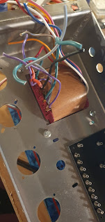
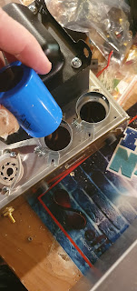
One thing led to another, and after finding out that I could remove one of the bellhousing side from the transformer, and that that it by some freak coincidence just perfectly fit in the transformer cut out of the JTM45 chassis.

OK, but at this stage, I still didn't know if the transformer was still good. I mean, I thought it was, but you never know. So I bolted transformer in, did a rudimentary connection to the mains, and then measured the HT windings and some others. Success! Not dead! And thus, a project was born!

I'd been toying with the idea of making a clone of the Fortin Meshuggah amp (yet another modded Marshall(tm) if you look at the schematic) so I kind of decided that I'd go down that path, and just use things I had, like the power transformer, and the chassis which fit together so nicely.

So, that was phase 1. I was going to build a clone of it. Awesome.

And I was going to do my own turret board as, well, why not...

But then, then things started happening...

I had this thought, which kind of came from really liking the forin 33 boost clone I'd built last year. I had a spare board. I could, you know, add that in. And I could make it switchable, via a front panel toggle. That would be cool I figured. 

Then I started thinking, i mean, what if I made it footswitchable? Wouldn't that be cool? 

This kind of opened the gates to feature creep somewhat. If you've ever worked in software, you'll know "feature creep" is where you get asked to build the program equivalent of a shoe. And then little things keep getting added, and before you know it, you're now making a shoe with jet engines, wheels, little wings, a satellite dish, miniature kettle and an anchor instead of brakes. So yeah, more things got added to the list.

So, boost board, cool, we can do that. But maybe I'd like to footswitch the 2 "channels" instead of swapping the input jacks to get the effect. OK, I reckon I can do that. Looks like it'll be a doubnle relay as channel 2 has a capacitor to ground. OK, I can do that...

So now we're up to 3 relays.

Then, then the next idea happened about 47 seconds after watching a lee jackson marshall mod video.

My brain tickled, and I asked "the" question. What if I wanted even more gain (because the meshuggah amp definitely does not have way more than enough gain already. And the boost won't have added any gain either at all... *cough cough*). That'd be a great idea. I can also make that switchable.

So there it happened. 4 relays.

And to make sure I didn't chicken out, 15 minutes later I'd drilled out a new tube socket hole in the chassis (first time for everything, it's a little off, but I can live with it, like 1-2mm closer to one tube than the other)

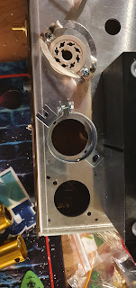
 No matter though, it's all about the intent. 

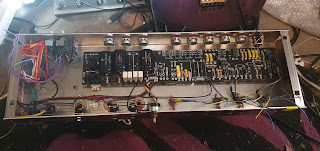
And to make the intent more intentfull, i went of and wired all the heaters to the sockets. And thus, mistake 1. I forgot the power tube sockets are bolted in 45 degrees off to what I am used to. Cue me wiring the heaters to pins 1+6 instead of 2+7. Stupid. Easy fix having spotted it now, but still stupid. Stupid as in if I hadn't of seen it now, it may well have caused some kind of fun tube or amp death and maybe magic smoke at some point. However, I'll never know as I caught it before it was too late. Phew!


Next bit, seeing as I was there, was fitting the cap cans. Here it turned out that the chassis was drilled thinking you'd be using a small little 45 or 50w power transformer, not a retarded big 100W one. Plus, the clamps I had, wouldn't fit, so I needed to redrill new holes. Eventually after enough procrastination, drilled them, just about fit, and m,ounted the cap cans. unfortunately, the clamps aren't dead centre around the hole, so the terminals on the cap cans look a little close to the chassis. I'll revisit when i wire them, and then maybe heatshrink, electrical tape, or most likely as it's the most fun, a hot glue gun, because, hot glue guns are awesome!


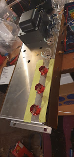
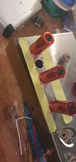
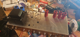
So there we have it. I've got ferrite beads on order, magical mustard caps, some sick as hell R


ussian radiation pilot lights, a 50w slo output transformer, 5H choke, and many other bits (actually, this is a lie, I have them already, but i wanted to build up suspense for next post)

I'm going to taking my time with this one, seeing as I'm doing a few things for the first time here, and this one might take a bit longer, but that's ok, as I'll hopefully learn a ton as I go along.


Wednesday 9 February 2022

Defeat snatched from the jaws of victory... And rescuing it back (a tale of idiocy and woe)

So I totally forgot to write anything for a while. Not because i'd stopped doing anything, but more because good intentions, and then just forgetting to, and, well, a slight mishap...

Anyway I finished the build beginning of June? Or something like that. Bit more wires than the sloclone, but got there in the end, even drew some skull on cross bones ontop of some caps to remind myself not to be stupid and lick them.

It all mostly went well, apart from that just like on the slo, the OT anode wires were the wrong way round again, and I found a mistake on the layout vs the schematic that meant i had no signal to the power amp. Important lesson here, trust the schematic, double check against the layout.

I'd done pretty well with neat wiring up to that point, but then had to concede and do a bit of rewiring and de soldering, but eventually, it all worked. Big thanks to the oracle for not getting sick of me, as I asked a lot of questions in the depths of despair...

So yeah, it came out really cool. I had some preconceptions about it maybe being too nice, but i think having the option of 20v zeners as well as stock Friedman values nicely added a bit of aggression to the amp, and it was brilliant! All was well with the world, apart from total inability to do woodwork (you should see the ghetto chicken door i made, and even did it without losing fingers, but it's definitely not an oil painting...)

But then, yeah, I killed it. Wondering why it stopped working, i was poking around in the amp, and here, dear reader, follows a tale of caution, entitled "don't be this stupid, and put dowen the screwdriver"

So, i decided, in infinite wisdom, to go tapping power tube pins with the screwdriver. The input jack I figured was iffy as it had been loose, but after tightening, and poking the wires, it was still not responding. Patient was braindead, but still had a pulse (ie, pilot light came on, transformers humming, valve heaters working).

All good. But does it make sound from the power amp? How shall I test this? I know, lets tap a pin with the screwdriver to make it go "pop", that way I'll be able to know it's the preamp.

What happened next was a moment of idiocy. The idiocy being that I thought this was a good idea. There was no voice of common sense sitting on my shoulder screamning "noooooo" (he'd gone on holiday to a day spa or something) so I did it. In went the screwdriver, and then, slip went the hand....

Now, we all like firreworks, they are cool, we like bangs too. Just not in an amp you've just built. The screwdriver (i think) shorted the pins between high tension supply and heaters. One big blue flas, and small bang, and now, nothing. All dead. No pilot light. No hum of transformers.

Dead.

Really Dead.

Really really dead.

Having taken stock, and after a fairly long period of silence staring at the amp, I checked the fuse. OK, so that's gone, maybe that's it.

I replaced the fuse. Still nothing. Measured voltages, nothing coming in at all. 

I looked, and looked, stared, consulted the (by now probably fed up) Oracle, but all to no avail. My diagnosis? Fried Power Transformer.

And thus, I left it. It had lived, briefly, and then died. Life happened. I did things, worked, summer went, the days grew shorter and it lay there forgotten. To repair it, I needed a new Power Transformer, and there was other stuff to do.

Then when i tried to order, the guy who makes them was unavailable. So again, the wait. 

Finally, beginning this year, i put a large order in. Not only was I going to fix it, but i was going to finish the second BE100 build I'd started, one that was using the Russian PCB I'd got (don't worry, I'll do a quick post on this one, as it's much the same as the BE100 build, unless, of course, it goes hilariously wrong, in which case the story might be longer).

So, got the transformers, and then one evening, not too long ago now, set about replacing the fried power transformer.

I even got some xt60 connectors so i could just plug it in, instead of desoldering from the board. These are cool by the way, used in RC cars, and can handle stupid amounts of current.  

So, I then, having rewired it, turned the amp on. Nothing. Nothing again. At this point my heart sank. Have i screwed it that badly that it's silently taken out the new PT? So I checked the fuse. All fine. Really, what is happening here?


Then, the penny, it dropped. The penny that read "Hey Stupid" on it. I checked the fuse holder. Now, it has two places the fuse can go. One is difficult to put it in, one is not. So i took the fuse from the difficult place, and put it in the easy to put place. 


Then, turned it back on. It works! Lights on, yes!!!! Still no sound, but, closer!   

So, time to have a look, and there it was, the culprit. A strand of shielded wire grounding the input to the chassis. That's what the problem was that caused all this mess.

So, as a result, I am now (after watching a lee jackson amp mod video) putting heat shrink on all the ends of shielded cables now, to avoid that happening. A rather long winded lesson I must say...

So, you may ask, does that mean the other Power tranny was fried? Well, not to spoil too much, but the answer to that question may very well involve subject matter for some future (not too far in the future) blog posts!

Meanwhile, here's some pics of incorrect, followed by correct places to put a fuse in an integrated mains IEC plug. Enjoy, and remember, I've been dumb so you don't have to be...


Anyway, until next time, when I'll be introducing a new project, and explaining how I will be torturing myself with this one.


Tuesday 11 May 2021

Let's do the twist, like we did last(this) summer

 Time for some wiring... kind of wanted this to be like the BE100, so instead of the neat parallel socket wiring on the slo, decided to do the full twisted wire experience. Which looked tedious and time consuming, and spolier alert, it is...

So, I also decided to do the whole twist a large length of wire using the door. This was pretty satisfying to be honest, and much easier than my last attempt, with a bonus of not bruising the living shit out of my legs. Pretty much tie wire to door handle, stand on other side of room, attach wires into drill, then slowly twist, and walk towards door. I ended up with a nice length, although some bits in the middle ended up a bit bobby, but seeing as I now had a lot of it, no problem, just cut the ugly bits out later. 

Anyway, I ended up with a rather long piece, as can be seen in the pics. Next up, roughly cut pieces with extra so i can wire between sockets and have it flush against the edge of the chassis later. Want it to look neat after all, especially as noone will ever see if aftrer the amp goes into it's home, but I will know it's there. and I'll have some nice pics for this blog. 


As a quick recap, twisted wires are so the distance between wires stays the same, and is one of those "reduce noise and hum from the AC voltage with 50/60Hz cycle hum from the power supply. There's a few other things you can do like elevating the heaters as well, which I'll be doing, but this is one of the bits that is quite important.


Anyway, lengths all cut, just lined them up where they were supposed to go. At this point I should have added the small tag board, but forgot. Ended up being a lot lot more fiddly to add this later, so I should have done it, like, at this point now. 

Not much else for this bit really, time to get out the soldering iron. And resist the temptation to lick it to test if it is on. Done it once, never ever ever again. Would NOT recommend.


So, wiring started. Choose a colour for each pin, and make sure this colour ALWAYS goes to that pin. Put the incoming AND outgoing wires in the socket pins (2 and 7 on octals) and wire. Then cut wire to next socket to length, and repeat the process. I actually found using the screw of the socket was handy as a guide to hold in place and loop. Also the alpha wire as it's quite stiff lends itself well to this. Just arrange, push into corner fold of chassis, run top next socket repeat.


Then, same with the preamp, sockets.

I read somewhere that whatever you tied to pin 2 on octal power sockets should go to pin 4+5 (which in AC are soldered together, and pin 9, the centre of the heaters for triodes (as a double heater, one for each side require 6.3V each, with DC you'd not connect 9 and just run 12V across 4 and 5 with them not soldered together))

pin 7 then goes to pin 9. 

I had them (as per pic) with a J shaped run down to 4+5, but a friend (not the oracle, but another version, lets call him the allknowing tinker, who is basically a mad scientist/amp tech I've know for years) pointed out this was bad, and to just run the wiring through the centre of the tube socket. So in later pics you'll see that change. Makes sense really. 

He also told of a prophecy that if you have different winds per twisted section per square inch for each of you runs (preamp run is one, power another etc) that this helps stop creating induction noise. If I'd known before I started this, I'd have done it for OCD, but at this stage of the game I'm going to leave it for the next build.


Lastly, as on a roll, I cut the wires to length from the output transformer to the impedance selector. Because I wanted a my little pony moment, I braided them together. I doin't know why. Just seemed like something I wanted to do, and as it's my amp, I'll do what I damn well like.

I do have to say that this took a lot longer than I thought it would, and was not really that much fun, but having done it, and it looking neat, I'm quite pleased with it for a first attempt, and everything would be awesome, except...

...excpet that having had a look at the layout diagram, the V1-3 tube sockets actually use a DC heater supply. Fuck. I've kind of decided that unless ithere is bad noise that I'll leave it like this. Rewiring will be a pain, not helped by having soldered together the 4+5 pins of every single socket, and the orientation of the sockets being upside down from the layout (something I bet I'll come to regret later on).

I'll just try to mitigate it by adding elevated heaters. Besides, the slo isn't that noisy, and that uses AC heaters through, even on the sensitive V1-2 tube gain stages.

I'm thinking I'll end up hot gluing the heater wires at strategic places once the amp is more done to hold them in place and for neatness, but maybe not. I'll see later on. I've also lost all those awesome plastic square things I used to tie down cable runs neatly in the last build, even though I know I have a huge bag of them. Maybe I should look a bit harder, as they'll definitely be useful.

Next up, it'll just be some power wiring to get rid of some of the long transformer leads which are definitely in the way.

Finally doing the dirty... drill me yeah baby yeah

 Oh yes, after lots of boring bits, bagging components, placing multiple orders, finally, finally, finally I've got round to doing something that is actually interesting. Also as I've neglected to post anything for a while, this could turn out to be quite long... I'll probably split it over a few to segregate by section of what i've been doing, so chassis work, mounting, heater wiring and hooking up power wires. Oh, I also seperated components into seperate boxes. One for chassis bits, other for electrical components. Reminds me I still haven't ordered the bits I forgot to get, should really get on that as there's a few things I didn't think of, and annoyingly, a few bits that were not on the BOM (even MORE annoying)

So, what have I been up to? I left you, dear reader, on a proverbial cliffhanger (well, maybe not, but if you're an accountant, or have a fetish for excel spreadsheets, I do apologize for the sheer amount of excitement contained in the last post). Since then, well, a lot of stuff involving power tools has happened. And screws. So If you get excited about drills, screws, nuts, bolts and twisted wires, then this post is most definitely for you, so go get your Kleenex, sit back, and in the words of Frankie Goes to Hollywood: "Relax"


Mr punchy the hole marker

Anyway, first off, I did a load of component mounting, and drilling of holes. To start off with, I positioned the PCB on the inside of the amp. Normally I'd choose a location like I did with the slo, but as the chassis was sort of predrilled already for the board the guy that makes them sells, I figured I'd try and use as many of the same holes, or at least one, if possible. Turns out, a few were there, but others, not so lucky. Took the board out, and marked the mount holes on the PCB with tape to be able to tell where they are. Then I positioned the board across as many of the preexisting holes already. Following that, taped the board down, and using a permanent marker marked the positions of the new holes. Simple enough eh? Also, I found this a bit easier than the last time where I used a cutout of a printed copy of the board. At least this way it means that you now it is to scale, as, well, it is the actual board and not a copy...


Following that, removed the board, use the punch marker thingy to punch a small indentation to use as a place to position the drill bit, and drilled pilot holes. Following that, drilled all of them out to 3mm with the appropriate drill bit. Then, as I don't like the look of screws sticking out from the chassis (pan heads) I went and countersunk all of them with the appropriate countersinking drill bit, which is just an invaluable tool. This time I have one that is standalone, and doesn't require clamping onto a drill bit. Means I'll hopefully break less drill bits. I've also been using an electric drill, whilst not as violent and quick as a mains one, it does mean I seem to be a bit more controlled, so that's nice. I did find, however, that when using the step drill bit with it that it is not powerful enough to actually do anything fun, so powered drill still rules for that...

So, once that was done, i found some standoffs (10mm) and figured I could use them, but quickly discovered that I can't as i'd need 5mm length screws either side. So I've ordered some 20 and 30mm ones. I'll have to figure out what I can get away with once I've populated the board and see how much clearance there is to the bottom of the chassis with those deliciously fat lethal voltage carrying capacitors (them smoothing ones for the power supply, the ones you don't want to lick unless you're either a little bit thick, or have a death wish). Besides, I'm also going to be mounting transformers and the choke, so there needs to be clearance for those bolts.

So next up, I went about mounting transformers and choke. Unlike last time where I made paper cut outs, I went with a place and mark approach like the PCB above. I used masking tape to help position (giving me an edge to line up the transformer against) and thus also allowing clearance on sides and front/back which I'll need for putting it into a headshell eventually. once positioned, I then used the same permanent marker to colour in the area where each bolt should go (4 per transformer, 2 for the choke). At this point for transformer orientation and placement I had a look at some online pics of a be100, and just roughly eyeballed it to be the same. 

Again, using mr punchy the metal poking hammer stick device, got small indents for the drill to be placed on, and drilled a pilot hole, then widened to 3mm, then widened to 5mm for transformers and 4mm for the choke. I'd found that when drilling the pcb mounts that I got burring on the inside of the chassis, and that that led to wonky strandoffs unless cleaned up, so I did a light countersink to tidy up the holes and remove excess metal from the inside of the chassis.

That all done, I used tape (again) with the transformer in place to mark out where I wanted to drill holes for the wires to go through. For the choke I reused a PCB mount point I somehow drilled out of position, in aid of that not going to waste. PCB has enough mount points so this isn't an issue, and also keeps things relatively neat without a random hole that when stared out asks many questions. That and it looks crap. At this point I got to use the step drill bit. Too much fun, so you've got to stop yourself from making massive holes and practice restraint. You don't want it looking like goatse, but more like a hole that is just the right size. Plus, you want a grommet to fit in it (nicve rubber surround to stop the chassis cutting into the wires, as as much as attaching a few hundred volts to what should be ground is, it's not advisable, as the effects thereof are apparently a lot less pleasant than what cartoons implied they'd be when you were a kid...


That all done, put the grommets in and then I mounted transformers with bolts after feeding through all the wires. I had forgotten to get some, but found out that racks screws are the exact size (M5) that I need, so used them. Plus, they were black, so matched the transformers. Colour coding is important you know. Mounted choke, and then all done for this bit.

Finally moved on and put all the tube sockets in. This bit ended up a bit more fiddly due to having put the transformers on first, and also because I'm adding shields for the preamp valves. Not the worst, but I'd probably do this first next time. Quite like the look of the gold shields, match the plexi panels. Kind of made me wish the chassis had a gold sheen to it on the outside, but, can't have everything. Besides, as I want an old school vintage plexi style headshell for this, you won't be seeing it anyway... Which also reminds me, I need to find the same stick on skull logo I used on the last build, but in drug dealer gold...

Then with them all bolted in, went and did the power sockets. Mounted this from the inside of the chassis, for a cleaner look, and this time actually added the valve retainers I didn't do on the last build (as forgot about them, until later on, at which point it was a pain to unbolt them and add them in, so, learnt that lesson for this build).

I also sort of solved the missing bias pot problem. As I ended up with a spare 25k linear pot, I drilled a hole for that just behind the power valves, so that the bias can be adjusted from there, hopefully shouldn't be too hard to reach, but figured it the only point it'd be viable to put it on the chassis that made sense. 

All in all not too hard, just takes a bit of restraint to stop yourself drilling holes in everything (there must be a term for it, drillaholeamania or something fancy in Greek/Latin). Also, as trhe chassis isn't powder coated on the inside, it's a lot less prep than the slo as you don't have to grind away the paint, which did take up a lot of time on the previous build, even if it did end up with some cool ass videos of sparks flying everywhere, and sparks, and fire, are always cool (and some would say essential parts of a metal video).

At this point figured it was time to stop, and also this post, as it's kind of covered this bit of the build. I've done more, but figure I'll just do separate posts for them to stop being long winded and boring.

More on that next time, as I'll actually be doing wiring things innit. Anyway, here, at the end, is a pic of how things are looking after this stage, and also the wires all tape inside to keep them out the way for the next few bits


Pic with filter for instawhoreagram


Thursday 6 May 2021

Bagged and Tagged

 Meant to write this yesterday, but didn't get round to it as, well, tedious tasks don't leave you buzzing afterwards...

So, what is this monotonous task devoid of all traces of Joy you may ask? Well, (un)interestingly enough, it's the prep phase of labeling everything you excitedly unpacked from a few boxes that some nice people presented to you on your doorstep, the items in question being a mouser, tube town and tube amp doctor order orders!

So, with one chassis filled with bags it's time for another really boring bit. Boring, but it will save mini meltdowns, tools being thrown across the room and swearing that'd make a whore blush at a later stage. It is time to bag and tag all the parts, and cross reference them against what you wanted in the first place.

Yes, it is tedious, yes it soaks up the best part of an evening, but from experience last time, it was a useful exercise and helps when it comes to actually building the amp.


Much like last time, process is simple and mind numbing:

- grab a bag

- see what's in it

- cross reference against the build BOM (bill of materials)

- tick off the bits you have


Usefully I seem to have everything now bar one order of capacitors that mouser didn't have, and had to be procured from ebay, so they could turn up like, whenever/any time, but they should turn up, otherwise it'll just end up adding a delay as I'll need to source them elsewhere.

Rather disappointingly though, I did notice a few mistakes that I need to rectify. The first of these being that I couldn't find the trim pot I wanted for the bias adjustment, and ordered another one. I really should have checked dimensions, as it turns out the pots i got are like trim pots for ants (zoolander style) and useless for this. Luckily though, i seem to have ordered an extra 25k pot, so I'll end up mounting that through the chassis. Probably a better solution, as it'll allow tube biasing without taking out the whole chassis, at least I hope it will... In any case as you can see, pot is way too small for the black board I am using. However, it does fit the Russian board I have spare, but I am not using that one for this build. When I use the Russian board, I'll be able to use it, or I'll find something else it is useful for, so they won't go to waste. Moral of the story? Look at dimensions of what you're ordering. Second moral of this tale: small trim pots for amp builds are nowhere near as funny as the stone henge stage prop in Spinal Tap.

Another fail was ordering the same switch 5 times instead of twice. Spares, I hear you cry, hoping to find a silver lining. Alas, numbnuts over here didn't see the different product codes when ordering at 1am, and should have ordered 2 + 3 other switches with 2 changed letters/numbers. This means I most likely will have to go and do a small top up order now, which is highly annoying. On the other hand, I need some 20V zener diodes for the modified fat/c45/sat board, so not all bad, and probably need some small other bits as well. Just annoying, that's all...

Talking of which, the Russian supplier of many things sent me a modded board. Along with the friendman be100 saturation circuit, he's done it so it'll take a 3 way DPDT switch, allowing me to add a different clipping style to the amp. So I get to either go 20V zener diodes, or red leds, or, well, whatever diode clipping I want to try. This should be cool. Luckily, also, one of the aforementioned numbnut orders too many switches switches should be usable for this, so, a slight silver lining there...

Anyway, boring task completed, the next step will be to actually do some actual work on the amp, and actually get started with stuff I can take pictures of and that you, dear reader, might actually care about rather than this boring admin Karen level drivel... 


I'll leave with a pictures of the final BOM with everything bar 2 or 3 bits all ticked off showing I have all the bits (almost) I need to start the build

Next time it'll be more interesting. I'll actually be doing stuff

Wednesday 7 April 2021

OCD wiring

 So looking back at my last built, I was kind of looking at the wiring and figured I could do better this time maybe. Then I saw a build "The Oracle" had done, and asked how he'd gotten things like bus wire and wtisted heater wires to look so good.

Now, you may remember last time I used a drill to make my twisted pairs, and lo and behold, this is still the best way (although the use of a door to stop it whipping your leg is a good idea...). Anyway, the below video is pretty much what I did last time and will again this, but without ending up with welts and bruises on your legs...


Now, the next video is so beautifully OCD, and by Blueglow electronics, who is just a diamond treasure trove of tips and information, and I count myself a massive fan (bar the intro music, which is clumsy) as he just disseminates so much brilliant information so well. Anyway, if you have EVER wondered how to get amazing looking bus/scaffolding wire that is straighter than a midwest conservative politician (although to be honest, they're probably hiding the exact opposite, repression and all) then this is the video for you. It's so satisfying, I am guessing there's probably individuals watching it for their own nefarious pleasure related purposes... I'm going to try both methods out, but the second looks like more of a winner due to rigidity...


 Right. After all that excitement I am off to take a cold shower...


Tuesday 6 April 2021

Best laid plans laid to waste

 This is more of a journey into the less fun bits. This time, component ordering (again).

So, last time, when I built the sloclone, I ended up ordering from way too many places, and had resolved not to do that again. However, it looks like this'll be happening again.

So, I was doing my order with Mouser, when I realised the relays I needed were like out of stock until late may/august, which was a bit of a showstopper. Damn it. Seems like the global silicon/parts shortage thing that is stopping gamers and bitcoin miners from indulging in over the top cards just hit home with respect to ancient technology. It also completely annhialated the "lets order things from one place only"

Add to that, that the rather nice impedance selector switch I wanted is now no longer made (the one I used in the sloclone) and add to that that the screw stash I thought I had, I actually didn't, and you've got another recipe for "order things from way too many places" again.

This is not the fun part. I'd forgotten. Kind of like getting a tattoo, you forget what it was like last time, and then when it starts, you remember.

Anyway, after 3 (yes 3) aborted/refused orders (RS components won't sell me stuff here unless i have a Belgian BTW number) I finally found one site via a friends recommendation called Reichelt in Germany. With a site in german. But I managed to find my precious relays, and at way less than mouser/RS was flogging them for, so that was a result. Probably ended up the same amount due to postage though, as nowhere seems to offer free postage...cheap skates (or maybe it is I who am the miser)

Anyway, my advice is to have a screw stash. Get a load of philips pan head m3 and m2.5 screws (16-20mm is what I am going for, as I think 16mm is enough to attach valve sockets without leaving a load of exposed screw, for neatness) a whole load of nuts for them, and some washers (and serated type ones as well, get a selection box). Also get a load of contersunk ones, as they're nice for mounting standoffs, 10mm/16mm probably good, maybe longer if you're using longer standoffs (depends what will fit in chassis though height wise, taking component height into account). Anyway, find a load, order a load. Get some m4 and m5 sets as well for your transformers and chokes, and m6 for mounting chassis.

So, basically, it's turning out like last time, where I am going to have to order from various places, and also reorder from places I have already ordered from, like, for instance, i forgot to order amp feet... I still need to do the component order, but I feel like I can probably entertain myself with mounting transformers, drilling holes to mount PCB and doing the heater wiring and other basic stuff and that that should keep me busy for a while.

Other non picture worthy progress is that I finally got hold of a V2 board layout so I can now see where everything is supposed to go, which is nice. I'm also going to have to start thinking of whether to see if I want to attempt to etch a board for the rear amp controls ( a few mini toggles) or wire them up as neatly as possible without with the switches in place... choices choices

Oh, and remember how I had hoped that the evil Bpost would actually ring my doorbell and deliver? They didn't. And I am stuck with no ID at the moment (screw you UK passport office for dragging your feet with my application) so I cannot pick it up. Which is utterly shit. Maybe I'll try tomorrow with a piece of paper and whinge at the old guy in the spar. Failing that, maybe I should break in after dark to retrieve my own parcel (not stealing if it belongs to you now is it)

In any case, it just means that it's taking a bit longer to get to the good stuff...

The moral of the story? Be a nerd. Love spreadsheets, do all your ordering at the same time and go and hit the big ones first, then slowly work your way down to more expensive specialist places. So, in this case, what I should have done:

- Order everything possible from Mouser

- Order from other electroonics specialists

- Order from niche places like Tubetown, Tube Amp Doctor etc

- Order from really obscure places that sell just those bits that you just cannot seem to find anywhere else.


I didn't, so I am back in this weird ordering hell where I am going to lose time having to wait for orders to show up, then figure out what I don't have, and then order that.

They say a donkey doesn't trip over the same stone twice over here in Belgium. So I am basically a sub donkey, whatever that animal happens to be...

Sunday 28 March 2021

Power Supplies...

 Just a quick one, but whilst watching the second video in the series (see below), towards the end there's a nice little nugget, that being a designer tool for power supplies. Awesome! Anyway, the goodness can be found here on Duncan's Amp Pages, and looks pretty nifty! Probably worth looking at if you want to design a PSU (or for referencing for myself for later use)

PSUD2 - Duncan's Amp Pages PSU Designer

 These videos if you mine them for little tidbits are proving really informative, so I am definitely sticking with them and recommending them.

 And here's the PSU video, which is a pretty good run through of how everything looks (as well as some nice stuff on screen resistor taps for linearity)


As a side note, looking at my output inMadOut output transformer, it has no screen grid tap, but going off the analysis being done in the videos of a fender amp, that does use one, so this is interesting. Something to make a mental note of. Another nice thing is pretty much having a "oooooooooooh" moment of the whole triode operation switches on the back of amps is pretty much a switch that just connects the screen grids (1 or 2 depending on if tetrode or pentode) to the plate. Seems like a simple mod to add later that just involves a simple switch...

Dusting off old knowledge and learning something new

 So, not much progress at the moment, other than i managed to order some parts (valve sockets, shields, IEC plugs, light, jewel covers to make power light pretty and other gubbins) so I'm not really going to go into that, other than that I have forgotten how to count, and for some reason thought the BE100 used 5 preamp tubes, when it actually only uses 4. So that was dumb, and as a result I'll have a 5th of all those parts. On the bright side, there's a margin for error, like, for instance, if the toolshed elves decide to steal 20% of my preamp parts, I'll have that covered...

This isn't about that, it's more about me having a slight panic. The reason for this is pretty much eh following. On my last (and first) build, there was a ton of docs out there. Boards well defined, loads of layout info, you name it, all there, so it was pretty much paint by numbers once I'd drawn the parts on the printouts of the PCBs.

This time however, less lucky. What I have are some layouts on a rev1 board, some boms, pics of an real BE100 inside, and some variant layouts (to build a JJ, maybe a phil X etc, basically, not sure, as just want to build the BE100 to start with). This would be all good and well, until I today decided to take one of the boards I have, and start soaking in the layout byu looking at what I had and the physical board.

The game of spot the difference (fun when you're a kid, keeps you quiet for ages) quickly turned into "try to spot the similarity" which is less fun when you're looking at a board that say "rev2". Quite a bit is moved, the board have no R or C labels (like r1, r2, r3, c1, c2..c30 etc) which then means either I:

a) time consumingly measure each connection on the board and see where it goes and draw out the board, then compare that to the circuit diagrams, and slowly build it up from that.

 b) try to look at the low res .png file of the rev2 board i found buried in the docs, and try and guess what some of the resistor and capacitor names are, as they are usefully in light grey on a white background, and even more usefully sometimes obscured and completely illegable by some kind of whatever.

c) buy another board set

or

d) panic...


The problems are:

a) I'll lose patience, and walk (head down, despondent) down the end of the road to have a conversation about the meaning of life with the goat and donkey who get tortured by visiting kids daily and have obviously accepted their sad lot and given up on the proposed topic of conversation(the donkey makes eeyore (or whatever his name is) look like an optimist). This path means this blog ends for another year whilst I end up doing things that are decisively less time consuming and dull (and frustrating)

b) Just means the above, but in a different form. My eyesight isn't good enough, and more importantly the png isn't high enough res by far, so the labels pixelate before you can get any clues out of them. 

c) Too stubborn. Not going to happen. I will prevail, if not today, then hopefully this decade.

d) Well, kind of went there. 

Anyway, so I spoke to the oracle (Tony). Decided to follow his advice of contacting the guy that made the boards, see if he has updated docs. Success, apparently tomorrow I should find something better. Even a translation from v1.0->2.0 of the board will do. I can then do some drawing by numbers.

So, in light of all of this, I kind of realized I had not understood the slo circuit when i built the amp and had just been soldering by numbers. I had meant to, but just didn't. And that kind of annoyed me a bit, as it was meant to be a learning experience as well.

What to do? Time to rectify the situation, and bridge the knowledge gap (see what I did there?)

So today I have been refreshing some electronics knowledge, having a look at simple tube based gain stage circuits and just ramming home what each little bit, resistor and cap kind of does on a simple level. Kind of let it soak in. The aim is that after a few days I can look at the BE100 schematic and know what each bit does, be able to break up the stages, understand the tone stack and in general see what I am building, and then hopefully percolate that so I can then know what mods do when I hopefully add some.

So yeah, that's the plan really, just dust off my degree from 21 years ago, become less rusty and start thinking in electronics for a while. 

Anyway, point is, I stumbled across the video below, and it really just gave me a "oh, that's cool, I get it" moment I'd been missing. I am working my way through the series and find it well explained. I've also been treating it a bit like a lecture, and been taking notes. I'm currently watch the PSU one. Tomorrow ("it's only a day away" - as sung by the ever optimistic orphan annie) I'll do the push pull section as a refresher, and work my way through them.

So, here's the video, worth a watch if you want a very simple run through of the various bits of a diagram as a start (wasn't my issue) and want a quick primer on a bunch of useful stuff and on the basics of pin out connections, what the load and bias resistors are, coupling caps, some quick other bits and where they live on a diagram. Sometimes it's better to see and hear rather than read.

Anyway, I reckon once I really get my head around the BE100, then the slo circuit gets revisited. Should stop me looking like a bit of a simpleton in front of The Oracle as well. Which would be nice. As asking tons of stupid questions just isn't good for one's ego...


Tuesday 23 March 2021

The long wait for bits and pieces to slowly show up...and then realising you still need to order the rest


So yeah, I've been waiting for some stuff from Russia to arrive, and haven't wanted to miss the doorbell, as otherwise the evil postman from BPost takes my long awaited package, and then deposits it at the local Spar (read: slightly larger than corner shop (and not on a corner) of disappointment that is never open at any hours to make it useful). The problem with this is that I still don't have a local ID card (blame bureaucracy and software issues) and have just sent off my passport for renewal in ze motherland, (which I might get back in 2-4 weeks? I don't know...). Unfortunately (and rather annoyingly, going int passive aggressive rage inducing) the guy there doesn't seem to think a drivers license, which has a photo, of my head no less, and my name (amazing) is sufficient.

This Russian cargo, I might add, is exciting, and pertinent to this blog. Let me explain. After seeing how nice the chassis was for the current BE100 clone build, I had a look at his other stuff, and then "by accident" (I swear, it is always by accident, I have twitchy mousefinger) I order a JTM45 chassis, another slo chassis, and a slo headshell and some grills (my excuse here being I still have a spare slo100 board, and it could be fun to build another one). Couple with, well, I'd like to build a point to point wired amp at some point as well. And the JTM45, being back from the 60s, aka, golden age of tubes, aka, really really simple circuits, shouldn't be too hard to do (plus it'll generate some "oh look I can use a soldering iron, please marvel at my joints and carefully selected components" instagram posts).

All of this, you probably didn't need to know, and you've been wondering "what the hell ahs all that verbal diarrhoea got to do with the damn picture". So, back to the doorbell.

So the doorbell goes, and as I've been watching tracking like a hawk, i run downstairs thinking it is the above. 

No such luck. Crappy Amazon parcel. Not very exciting. So I kind of gave up for the day, thinking, maybe tomorrow... 

However, in my morning malaise (after feeding the chickens, henceforth referred to as the consumers of all things) walking back to the back of the house I noticed a box. On closer inspection, said box was heavy. I also had no idea of what was in it, or why it had Belgium misspelt as Belgio. 

Suddenly, realisation, these are transformers! I'd literally forgotten I had ordered them from the rather excellent InMadOut. Only slight niggle is that he refused to paint them Donald Trump toilet seat gold (to match the chassis), but other than that, again, they look fantastic. Very pleased with them, even if they are still loose. They seem large and chunky which is nice as well.

Anyway, part of the BE100 build had a separate 14v transformer as a requirement. When I asked InMadOut about it, Magneto (forgotten real name, but as it's magnet related, the new name for him is apt) suggested he just added it as another tap on the mains transformer. So this has a 14V tap, which will be used for the relays I believe. Which is cool, as it'll be less clutter.

Choke looks quite chunky as well. As the BE100 chassis isn't as deep as the slo clone one from previous posts, I don't think I'll be able to mount it internally, but I figure as the amp will have solid front, and have air vents in top and rear, that I shouldn't really get too carried away by making things look pretty on the inside. Yes, contrary to popular belief, beauty is on the outside, not in.

The arrival of the tranformers also means that I now should really get the component order sorted out, as well as order tube sockets and various other bits and pieces from tube town.  

 On top of this, and I'd almost forgotten about it, a friend of mine sent me some extra infor on some choice mods he made to his BE100 build. I kind of like the idea of being able to switch between the 4 and 16ohm tap for the negative feedback loop. I also think that unless the BE100 already has it (haven't studied the schematic well enough) I'll add an elevated heater mod here as well.

In any case, amp build D Day is approaching, and I do plan to do some videos like last time, as they came out quite cool (well, I thought so anyway).

So, hopefully reading this inane drivel has kept you off the streets and out of trouble for a few minutes, and next time I might actually do an update that involves something other than "here's what I got in the mail"

Tuesday 9 March 2021

It's been a while...

You know when you do something really fun? And the end result is awesome? And then somehow you descend into other spheres of OCD madness? In my case this was a car obsession for a while, then I dabbled in pedals, but I've kind of realized that it has been 5 years since I built the last amp and that's a bit too long... 

Not only that, but I think completely fucking up the power board of the 5150 trying to get it out (they REALLY don't want you to remove it on the first run, i mean, it is literally riveted on WTF) and then messing it up even more thinking I knew what I was doing but then melting the tracks off the board... well, that little experiment cost me a new board from peavey, so i just retolexed the bastard  amp and put it back together with new power board. 

Anyway, you don't want to hear about that, do you, you're not my unknown virtual agony aunt, who I tell of all my woes, you're not my virtual shoulder to weep crocodile tears on in a pathetic attempt to gain some insincere sympathy and all that crap... No, you're here to read my adventures and mishaps as I go for amp build #2! 


So, what is this build then? Well, about 3 years ago or so I bought 3 PCB boards of a nice chap in a trenchcoat in a tube station back in misty London town, in something akin to a drug deal gone geek. After this encounter, and with what looked like (and still do) some very high quality PCBs from a limited run I was convinced I had the get up and go to go off and build. The amp in question? A clone of the Friedman BE100. 


As I didn't have a Marshall style amp at the time, I figured, hey, why not. But then, well, you know, things go wrong, and you start making excuses, and you can't find a suitable chassis, and then you end up too lethargic to order transformers, and then you buy a car with issues and then get obsessed with fixing that, and all of a sudden, years go by... Anyway, Tony (still referred to as the Oracle) just randomly sends me a link to this Russian dude selling a chassis that looks remarkably exactly like the chassis I need. I have been half heartedly looking by this point, but not really that hard, and have been put off by the needing to get a custom faceplate. However, this has it all, it is like the miss world of chassis (at this point at least, we'll find out when we start putting shit in it, i mean, parts). So praise the lords of metal, and one click later at 3am half asleep thanks to ebay I've bought it. Awesome. Anyway, so that arrives, and it is actually pretty cool. May have to drill extra holes, as they don't line up with my board (but if I'd got the boards he is selling it'd have been a perfect fit, so I can't complain, even though whinging about irrelevant crap is baked into human nature). Faceplates look cool too, so it's all good!

Anyway, having got the chassis, I've just placed an order for the transformers from InMadOut, the same source as the ones for the slo clone build. Had them slightly changed, so that I have a 14V tap from the PT to save me adding another small 14V transformer. Whether this is a good idea, I don't know, might be a reason it's separate on the Friedman, but as it's powering relays, probably just some form of cork sniffing. I have no idea, but I guess I'll find out... Regrettably InMadOut wouldn't spray the casing gold for me (probably as they are helping me to not make the amp look like donald trump's bathroom interior) so I've had to settle for matte black instead. Black is good. We like black. It sucks in light, and as everyone knows, black objects go faster and sound better. Fact.

So, what else? I've got to do a order for tube sockets, knobs (either Friedman style or Marshall style I think) and need to get gold tube sockets (not the pins, but the surround, for looks, which will be a waste of money seeing as it's going to end up in a vintage style marshall-esque headshell which has no front grille, but much like a penis extension, I'll know it's there, and that's what matters)


After that it'll be the hate job, ie, putting together the order of components from mouser (or wherever is best now I've fled to Europe), choosing capacitors for cork sniffing reasons, and invariably being over the top and getting components with stupidly tight tolerances that are overspecced. Because, as the Mandalorian says, this is the way.

Anyway, probably be a while before next update, unless anyone gets really excited about unboxing videos, n which case tough, you're going to have to get your weird fetish kick somewhere else, as unboxing videos are invariably awful and an anti-climax (unless, you are that fetish person, in which case most like the opposite)

So anyway, until next time, when hopefully some interesting shit will happen and be written about.

Wednesday 30 March 2016

End of my frst foray into amp building: Tolexing and putting it together, the end result

Right, so last time I just had the tolexing left to do, and thanks to some sunny weather over the weekend it got done. I was dreading it, expecting it to go pretty wrong, but, as I discovered, it's actually fairly easy, well, easier than you'd imagine.

First up, you will need, some tolex, cut to be enough to wrap round the amp with some overhang. You will need spray glue (instant adhesive stuff that you spray, wait 2-3 minutes for it to go tacky and then stick) and an exacto/hobby knife, and, well, that's it.

Process is really easy too. Wrap it round the amp, line it up, then peel back, and just start doing each side. I could explain it, but this youtube video does a far better job of explaining it all, and is what I used as a guide. Also, it really is tre that the corners can be messy, mine weren't all that great, but the amp corners hide it all, so that really does make up for any slight miscuts you do.

The seem was also fairly easy, although next time I'd do it in the middle of the base of the amp, as doing it at the side was a little bit fiddly, or I'd at least line it up so it was exactly to one side, ie, the bottom fold just slots straight into the base of the cabinet. Anyway, lessons learnt.


And well, that's pretty much it. About 1-2 hours work in all, poke the holes for chassis mount, handle mount etc through with a small sharp thing, screw on the corners to hide any weirdness in the corners (ie, mistakes), add handle and done!

I also mounted the front grill to the head cabinet using screws on the side, which gives a cool look.

Anyway, after that, just a case of slotting in the amp, screwing it in via chassis mounting screws (which in my case double up as amp feet, which is pretty usefull) and voila, one finished amp! Looks pretty damn cool eh? Really glad I went with the snakeskin, it's a very cool look for a cool amp. Really pleased how it turned out, and now thinking of what I want to make next!