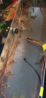
So, I also decided to do the whole twist a large length of wire using the door. This was pretty satisfying to be honest, and much easier than my last attempt, with a bonus of not bruising the living shit out of my legs. Pretty much tie wire to door handle, stand on other side of room, attach wires into drill, then slowly twist, and walk towards door. I ended up with a nice length, although some bits in the middle ended up a bit bobby, but seeing as I now had a lot of it, no problem, just cut the ugly bits out later.
Anyway, I ended up with a rather long piece, as can be seen in the pics. Next up, roughly cut pieces with extra so i can wire between sockets and have it flush against the edge of the chassis later. Want it to look neat after all, especially as noone will ever see if aftrer the amp goes into it's home, but I will know it's there. and I'll have some nice pics for this blog.
As a quick recap, twisted wires are so the distance between wires stays the same, and is one of those "reduce noise and hum from the AC voltage with 50/60Hz cycle hum from the power supply. There's a few other things you can do like elevating the heaters as well, which I'll be doing, but this is one of the bits that is quite important.
Anyway, lengths all cut, just lined them up where they were supposed to go. At this point I should have added the small tag board, but forgot. Ended up being a lot lot more fiddly to add this later, so I should have done it, like, at this point now.
Not much else for this bit really, time to get out the soldering iron. And resist the temptation to lick it to test if it is on. Done it once, never ever ever again. Would NOT recommend.
So, wiring started. Choose a colour for each pin, and make sure this colour ALWAYS goes to that pin. Put the incoming AND outgoing wires in the socket pins (2 and 7 on octals) and wire. Then cut wire to next socket to length, and repeat the process. I actually found using the screw of the socket was handy as a guide to hold in place and loop. Also the alpha wire as it's quite stiff lends itself well to this. Just arrange, push into corner fold of chassis, run top next socket repeat.
Then, same with the preamp, sockets.
I read somewhere that whatever you tied to pin 2 on octal power sockets should go to pin 4+5 (which in AC are soldered together, and pin 9, the centre of the heaters for triodes (as a double heater, one for each side require 6.3V each, with DC you'd not connect 9 and just run 12V across 4 and 5 with them not soldered together))
pin 7 then goes to pin 9.
I had them (as per pic) with a J shaped run down to 4+5, but a friend (not the oracle, but another version, lets call him the allknowing tinker, who is basically a mad scientist/amp tech I've know for years) pointed out this was bad, and to just run the wiring through the centre of the tube socket. So in later pics you'll see that change. Makes sense really.
He also told of a prophecy that if you have different winds per twisted section per square inch for each of you runs (preamp run is one, power another etc) that this helps stop creating induction noise. If I'd known before I started this, I'd have done it for OCD, but at this stage of the game I'm going to leave it for the next build.
Lastly, as on a roll, I cut the wires to length from the output transformer to the impedance selector. Because I wanted a my little pony moment, I braided them together. I doin't know why. Just seemed like something I wanted to do, and as it's my amp, I'll do what I damn well like.
I do have to say that this took a lot longer than I thought it would, and was not really that much fun, but having done it, and it looking neat, I'm quite pleased with it for a first attempt, and everything would be awesome, except...
...excpet that having had a look at the layout diagram, the V1-3 tube sockets actually use a DC heater supply. Fuck. I've kind of decided that unless ithere is bad noise that I'll leave it like this. Rewiring will be a pain, not helped by having soldered together the 4+5 pins of every single socket, and the orientation of the sockets being upside down from the layout (something I bet I'll come to regret later on).
I'll just try to mitigate it by adding elevated heaters. Besides, the slo isn't that noisy, and that uses AC heaters through, even on the sensitive V1-2 tube gain stages.
I'm thinking I'll end up hot gluing the heater wires at strategic places once the amp is more done to hold them in place and for neatness, but maybe not. I'll see later on. I've also lost all those awesome plastic square things I used to tie down cable runs neatly in the last build, even though I know I have a huge bag of them. Maybe I should look a bit harder, as they'll definitely be useful.
Next up, it'll just be some power wiring to get rid of some of the long transformer leads which are definitely in the way.


No comments:
Post a Comment